Below, I'll explain the main features of each type of 3D mesh that can be created.
To work with both types of 3D meshes, I recommend using a top-down view in the editor, as if you were designing the perimeter in the case of "Shapes" or the layout in the case of "Roads." Creating them in 2D is much simpler than in 3D, although actually, by creating "walls" for the 2D shapes you design, the resulting meshes are 3D, allowing you to configure the height of the "walls."
Thus, both Shapes and Roads are created as 2D shapes with a height that converts them to 3D, and the surfaces are flat. However, in the case of Roads, I wanted to create a gradient in the layout because otherwise, they would look a bit dull. The proposed solution is through an "Animation Curve" displayed in the editor where the desired "height map" for each ROAD is established. This solution allows, for example, if I have the "height map" of a real circuit and reproduce it in the "Animation Curve," creating a ROAD similar to the circuit in question and assigning it that "Animation Curve," with minimal effort I would obtain a circuit similar to the real one. The beginning and end of the "Animation Curve" must be at the same height to avoid a sudden jump in the layout.
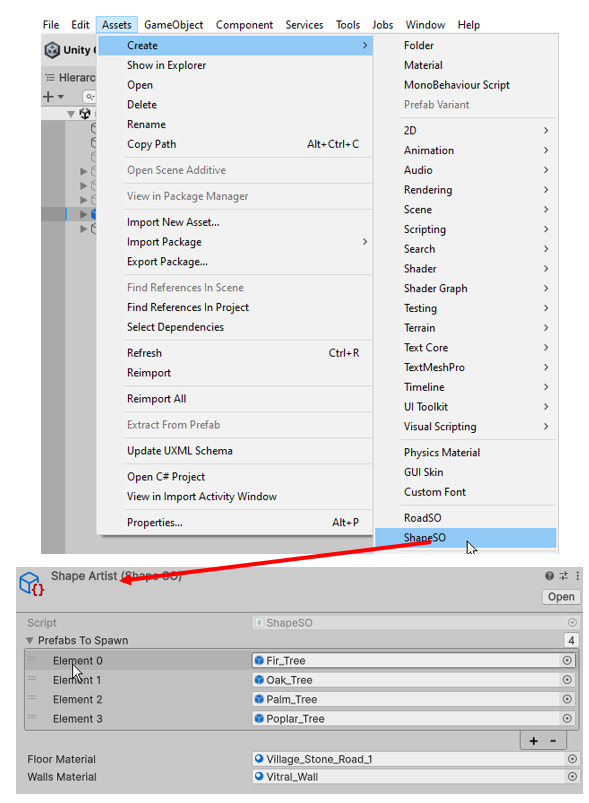
Drag a “SHAPEPREFAB” prefab into the scene or create an empty game object and add a “ShapeCreator” component to it.
If you're starting from an empty game object, you'll need to create a "ShapeSO" scriptable object asset (link the desired materials and prefabs to spawn to the new "ShapeSO") and assign it to the editor in the variable provided for this purpose in the "ShapeCreator" component.
It's recommended to create a library with "ShapeSO" assets and create and populate it as "Skins" that define the visual appearance of the SHAPES.
The "ShapeCreator" component represents the entire user interface exposed to create SHAPES and assign them a "Skin" ("ShapeSO" asset). It's that simple.
The versatility of the SHAPES creation algorithm is extremely high. The design can start from the definition of a few points, and then create a resulting "mesh" with a much higher resolution depending on the "Evenly Spaced Points Step" parameter, moving from very angular shapes to rounded ones.
The Shape editing commands in the Scene view are:
-
Shift-left click on empty space to create new shape.
-
CapsLock-Left click to add points.
-
Shift-left click on point to delete.
-
Left click on over the mouse point to drag and drop position to desired spot.
Rules of the SHAPE creation algorithm:
-
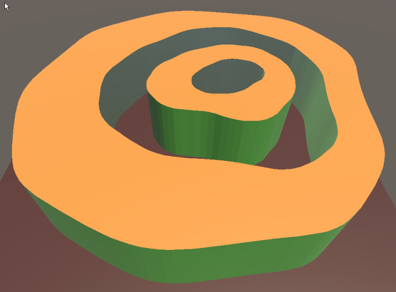
A shape 100% inside another shape creates a hole inside the second.
-
A shape 100% inside another shape 100% inside another shape creates a new shape inside the egg created by the first two, and so on. In the example, by creating four shapes with fewer than 10 points each (less than 40 mouse clicks), I create the next SHAPE in a few seconds with just one click of the "Create Paths" button.
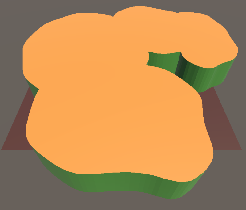
-
A shape not 100% included within another creates a shape resulting from the superposition of the two. In the example, by creating four shapes with less than 10 points each (less than 40 mouse clicks), I create the following “SHAPE” in a few seconds by simply pressing the “Create Paths” button.
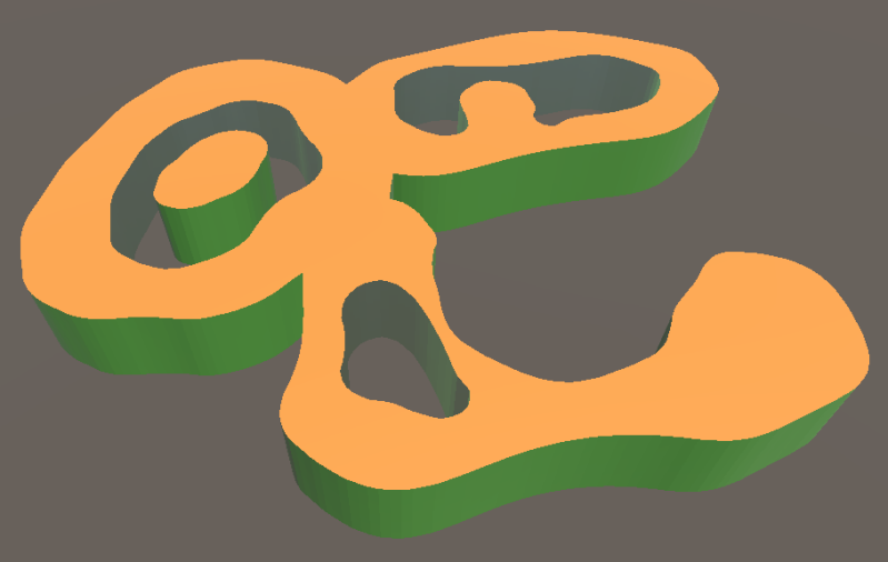
-
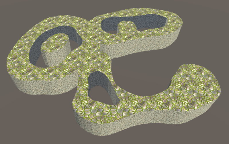
Combining the two previous rules. In the example, by creating seven shapes with fewer than 10 points each (less than 70 mouse clicks), I create the following “SHAPE” in a few seconds by simply pressing the “Create Paths” button.
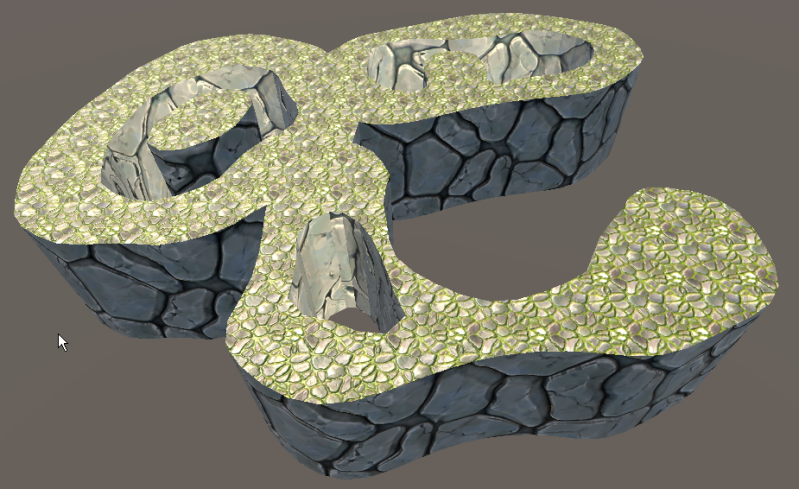
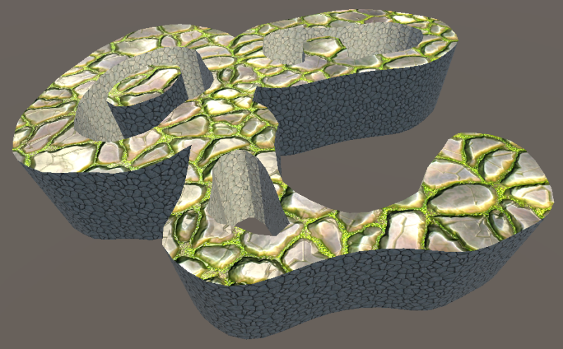
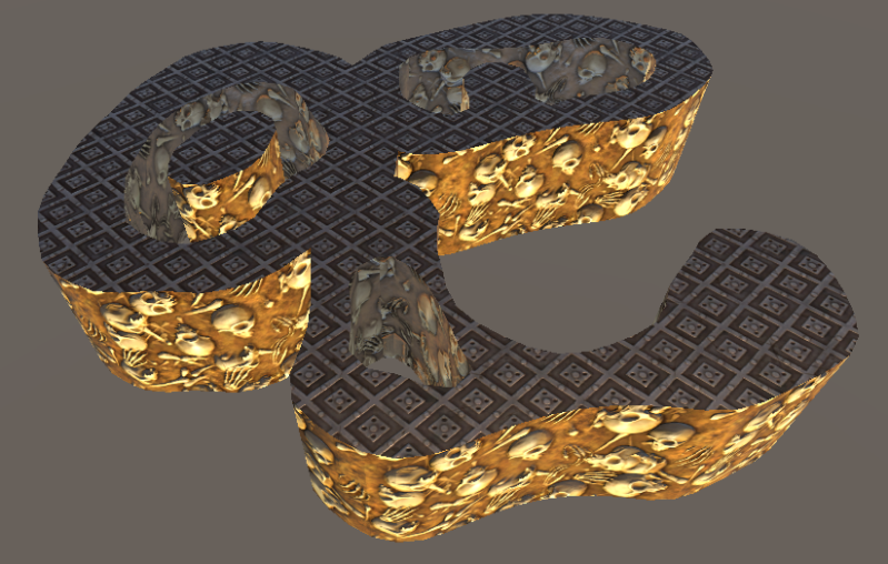
• If I use artist-created materials instead of using texture-free materials, the results change dramatically with minimal effort. “JOIN THE DOTS 3D SHAPES & ROADS” automatically performs the necessary calculations to correctly display the textures of the assigned materials, and you can adjust the scale with the following parameters:
The textured material applied to the walls must be set to “Render Face” = “Both”.
-
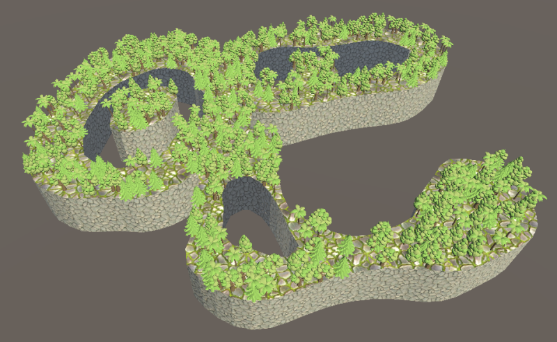
If I also press the “Spawn Props” button and check that the “Prefabs To Spawn” list is correctly assigned and that the following “tags” necessary for the correct functioning of the “Spawn System” exist: “SpawnableShape” and “SpawnManager”, the result is spectacular for the effort and time spent to achieve it.
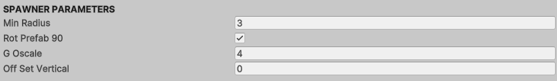
The parameters to control the “Spawn System” are self explanatory except for the first “MinRadius” which sets the density of created elements.
The parameters not yet explained within the “ShapeCreator” component are quite intuitive. The radius handle defines the size of the gizmos, allowing me to manually vary the position of each point in the SHAPE to adapt to the scale I'm working at, so the size never becomes inconvenient to manipulate.
As for “WallsHeight”, well, that’s it…
SHAPES are created along the XZ axis in the desired position, and can be fine-tuned using the mouse (drag & drop). The Y axis, i.e., the height position, is adjusted from the editor or scene view using the transform.position.y parameter of the shapeMesh child game object.
As an additional explanation, the system is designed to not touch the transforms of any of the three GOs that make up the SHAPE Creator. The parent has the user interface (“ShapeCreator” component), the child represents the 2D surface I designed, with its “transform.position.y” setting the height position of the SHAPE, and the child of the child represents the wall that converts the SHAPEs into “3D shapes.”
If I want shapes at a different height, I'll need to create one in an additional game object (or drag another prefab into the scene), to which I can assign a different skin.
I recommend that when dragging a SHAPEPREFAB into the scene, right-click on the prefab selected -> prefab -> unpack completely.
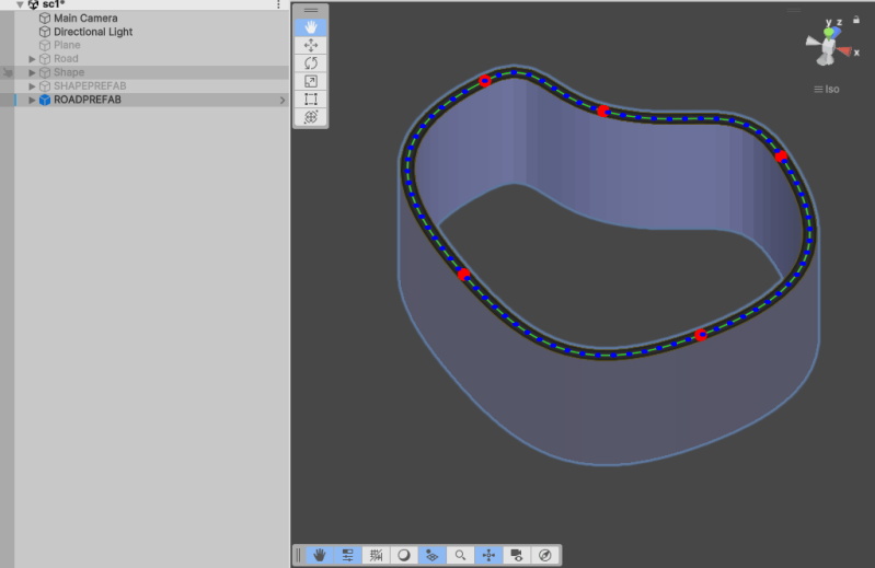
Drag a “ROADPREFAB” type prefab into the scene or create an empty game object and add a “RoadCreator” component to it.
Aparecerá una ROAD con la que empezar a trabajar.
If you're starting from an empty game object, you'll need to create a scriptable "RoadSO" object asset (link the desired materials to the new "RoadSO") and assign it in the editor to the variable provided for this purpose in the "RoadCreator" component.
It's recommended to create a library with "RoadSO" and create and populate it as "Skins" that define the visual appearance of the ROADS.
The "RoadCreator" component represents the entire user interface exposed for creating ROADS and assigning them a "Skin" ("RoadSO" asset). It's that simple.
The design can start from the definition of a few points, to subsequently create a resulting “mesh” with a resolution that will depend on the “Evenly Spaced Points Step” parameter displayed in the “PathCreatorRoad” component that is automatically added, allowing the design of shapes from more angular to more rounded.
The Roads editing commands in the Scene view are:
-
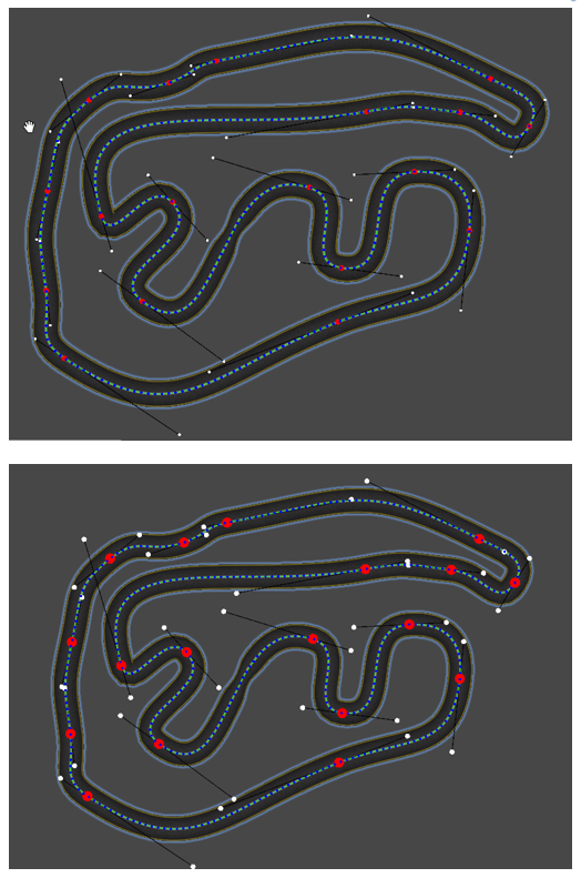
Left click drag and drop on road anchor point (red) to edit position.
-
When you hold Ctrl close enough to a road segment it enlights yellow.
-
Ctrl-left click close to a segment(enlighted) to add a road position.
-
CapsLock-Left click with mouse over point to erase point.
-
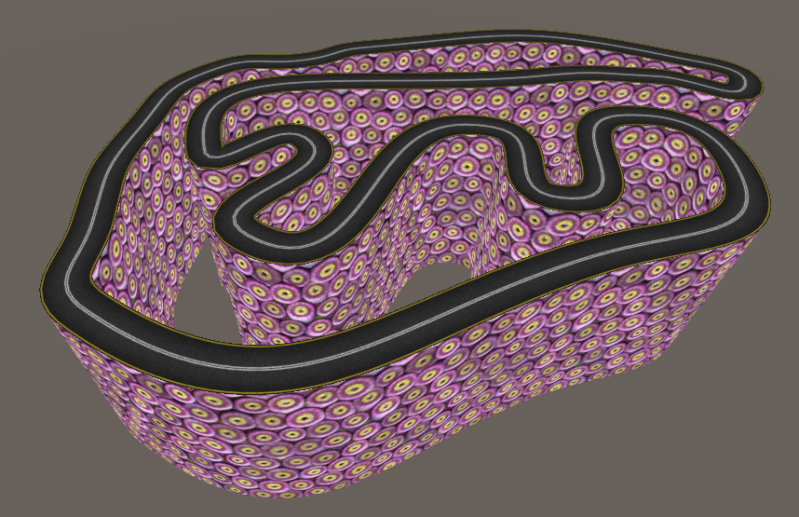
If I use artist-created materials instead of using texture-free materials, the results change dramatically with minimal effort. “JOIN THE DOTS 3D SHAPES & ROADS” automatically performs the necessary calculations to correctly display the textures of the assigned materials, and you can adjust the scale with the following parameters
The textured material applied to the walls must be set to “Render Face” = “Both”.
The parameters not yet explained within the “RoadCreator” component are quite intuitive. “Road width” defines the width of the road.
As for “WallsHeight”, well, that’s it…
If you push the “Create New” button, be careful as the existing one will be erased. To create a new additional road, drag and drop a new ROADPREFAB to the scene.
Now we'll move on to explaining the configuration parameters within the “PathCreatorRoad” component.
In the case of the ROADS, I wanted to create a gradient in their layout because, otherwise, they would look a bit dull. The proposed solution is through an "Animation Curve" displayed in the editor where the "height map" I want each ROAD to have is established. This solution allows, for example, if I have the "height map" of a real circuit and I reproduce it in the "Animation Curve," creating a ROAD similar to the circuit in question and assigning it that "Animation Curve," with minimal effort I would obtain a circuit similar to the real one. The beginning and end of the "Animation Curve" must be at the same elevation to avoid a sudden jump in the layout.
The bool parameter “Use Curve” defines whether or not the “Animation Curve” is applied. If the “Animation Curve” is applied, it must be created first.
The “Height Factor” parameter will define the intensity of the relief created.
As explained before, the mesh resolution is calibrated with the "Evenly Spaced Points Step" parameter, and the "Auto Set Control Points" bool creates a harmonious Bezier curve. If we set the bool to false, we can fine-tune the shape of our road, displaying additional gizmos in the scene view as white discs representing control points for each point on the curve.
The "Anchor Diameter" and "Control Diameter" parameters set the size of the "gizmos" for our road's points and control points, respectively. This ensures we can work comfortably at any scale in our design.
ROADS are created on the XZ axis in the desired position, and these positions can be fine-tuned using the mouse (drag and drop). The Y axis, i.e., the height position, is adjusted from the editor or scene view using the transform.position.y parameter of the shapeMesh child game object.
As an additional explanation, the system is designed to avoid touching the transforms of any of the three GOs that make up the ROAD Creator. The parent contains the user interface ("RoadCreator" and “PathCreatorRoad” components), the child Game Object represents the 2D surface I designed, with its "transform.position.y" setting the height position of the ROAD, and the child Game Object represents the wall that converts the SHAPES into 3D shapes.
If I want a ROAD at a different height, I'll need to create one in an additional Game Object (or drag another prefab into the scene), to which I can assign a different skin.
I recommend that when dragging a ROADPREFAB into the scene, right-click on the prefab selected, then right-click -> prefab -> unpack completely.


Crea tu propia página web con Webador